Analog Multimeter Circuit Diagram Pdf
Current is the measure of the rate of electron flow in a circuit. A better source according to Team X is the interconnect diagram which is a visual wiring diagram that shows the sensor and all of its associated wiring so theres no guesswork.
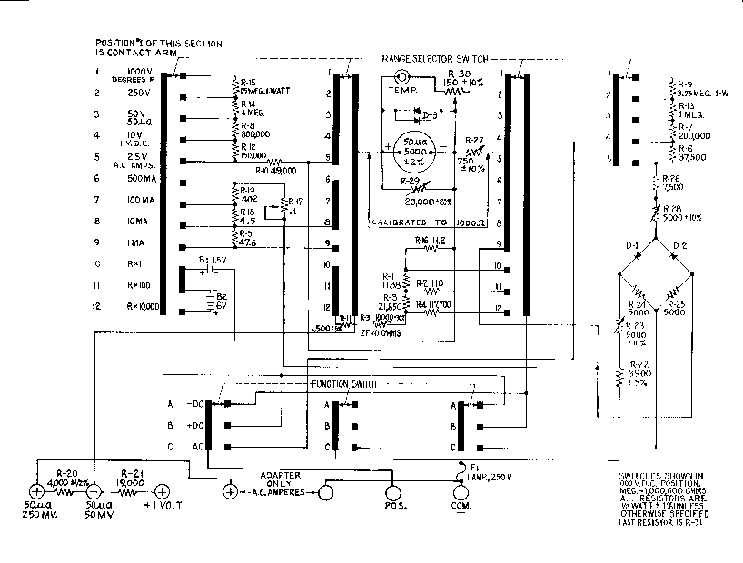
Simpson 255 Analog Multimeter Schematic Sch Service Manual Download Schematics Eeprom Repair Info For Electronics Experts
Figure 4 shows the circuit diagram for the radio.

. Most of the cellphone technician. Bus off P1797 CAN TCMECM Circuit Malfunction P1798 CAN TCMINST Circuit MalfunctionFeb 16 2017 Feb 16 2017. For its time this was an extremely fast device 40MHz and is capable of providing all of the sound processing needed in a WPC pinball machine.
The Capacitor Handbook Comprehensive Guide For Correct Component Selection In All Circuit Applications. The capacitor and adjustable coil. 13 Before returning your digital Multimeter for repair be sure to check that the fail- ure to operate properly is not due to the following.
RETURN FOR REPAIR Sec. A CAN bus failure will mean modules are unable to communicate and may. Circuit capacitors discharge before you start working on the drive motor or motor cable.
Finally remove the digital multimeter wire the load and run it. Its worthy to notice that tuning of one. This circuit measures the speed of a cricket ball based on the time taken by the ball to travel the distance from the bowling crease to the batting crease 25.
Item 37772 61593 For technical questions please call 1-888-866-5797. Do not switch between testing modes with the multimeter connected to a circuit. This is what allows you to tune into a certain station.
There is no voltage between terminals BRK and BRK- and the ground. Download mobile phone circuit diagram book pdf the Best way to get complete information on mobiles diagrams. Signals are multiplexed onto this pair of wires to enable communication between modules.
The contact in parallel with the Run switch is often referred to as a seal-in contact because it seals the momentary condition of the Run switch closure after that switch is de-actuated. On a side note in the. An integrated circuit or monolithic integrated circuit also referred to as an IC a chip or a microchip is a set of electronic circuits on one small flat piece or chip of semiconductor material usually silicon.
Click all mobile circuit diagram in pdf to watch 18 mobile circuit diagram on your device right now. Then put the multimeter in proper current range and adjust the I-ADJ trimpot to get 10A readout. Higher than 20 amps.
Open loose or intermittent test leads. Large numbers of tiny MOSFETs metaloxidesemiconductor field-effect transistors integrate into a small chipThis results in circuits that are orders of. If these conditions do not exist and the instrument fails to operate properly return the instrument and accessories prepaid to.
AC Current Measurements only use. And get your specific engine rightGarmin has sensor wiring examples for Lycoming Continental Rotax and Jabiru engines with a drawing for UL Power FADEC as well. CAN is a pair of wires linking control modules throughout the car.
In the circuit you will build the capacitor has a fixed value but when you move the tuner along the receiver coil you change the inductance of the coil and thus the resonant frequency of the circuit. Selection of proper meter range Ammeter Schematic Diagram. Mobile circuit diagram.
How to measure current with a multimeter. This circuit is known as a latching circuit because it latches in the on state after a momentary action. How to check a multimeters internal fuse.
The follow-up question of how we may make the motor stop running is a. Always ensure by measuring with a multimeter impedance at least 1 Mohm that. Page 7 Do not test current on circuits multimeter and the fuse may blow.
Get A Free mobile phone circuit diagram pdf. It is measured in the unit of the Ampere simply called Amp A. The board dropped the microprocessor controlled synthesizer chip and sound bite system of earlier WPC machines and replaced them with the still in production Analog Devices ADSP-2105 DSP.
You can watch it before download it on your mobile. There is no voltage between the drive input phases U1 V1 and W1 and the ground. 978-0962852534 - product description This book provides practical guidance and application information when using capacitors in electronics and.
General Operating Instructions 20 amperes. Power up the module and connect a digital multimeter dialed to proper dc voltage range across the output connector and adjust the V-ADJ trimpot to get 90VDC readout.
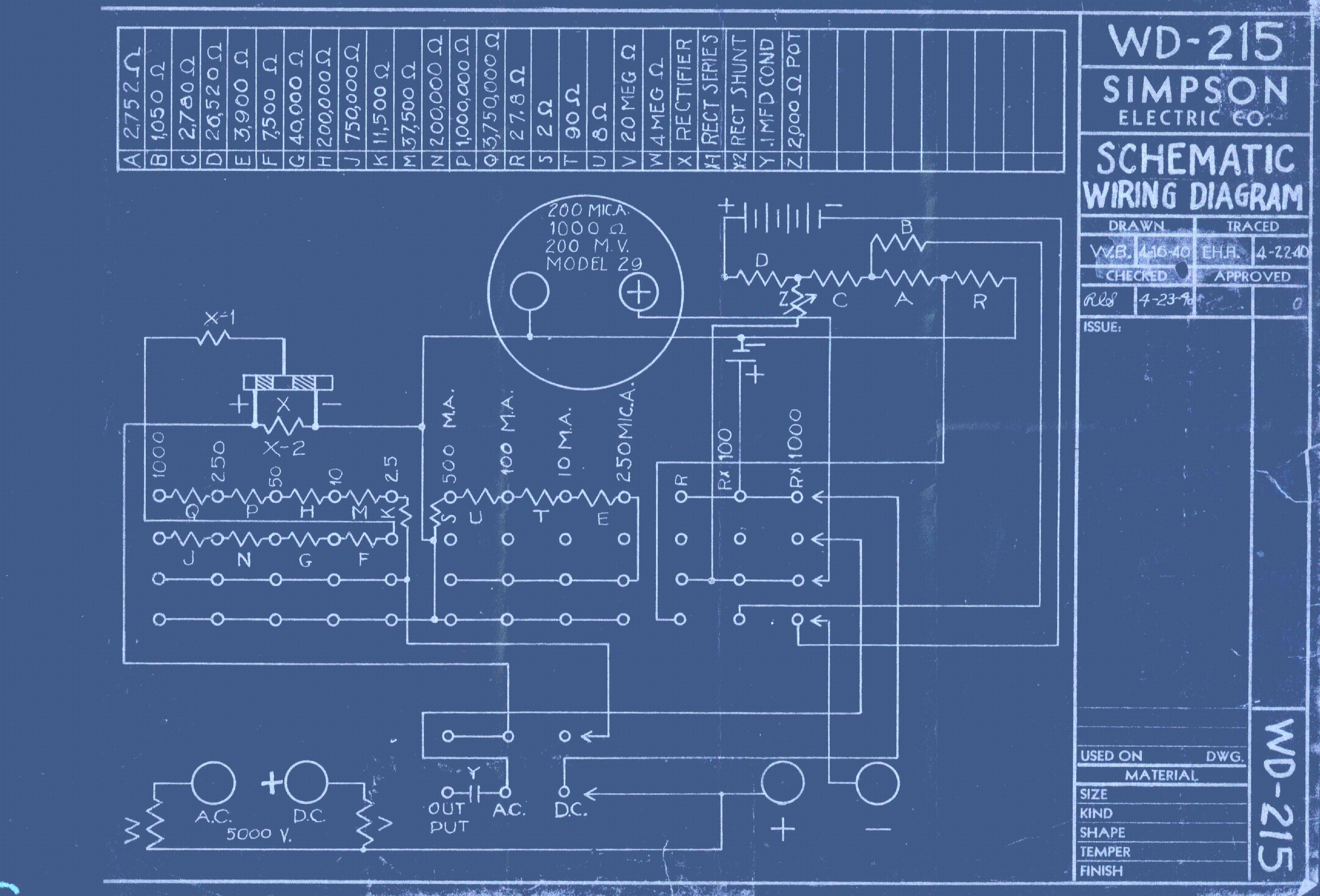
Simpson 215 Analog Multimeter Schematic Sch Service Manual Download Schematics Eeprom Repair Info For Electronics Experts
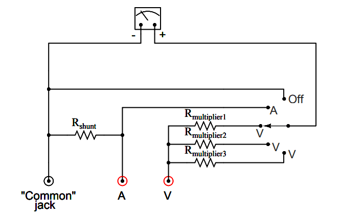
Multimeter Schematic Circuit Instrumentationtools
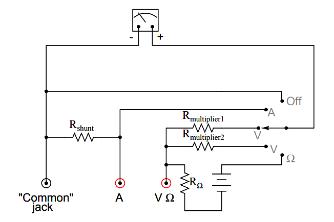
Multimeter Schematic Circuit Instrumentationtools
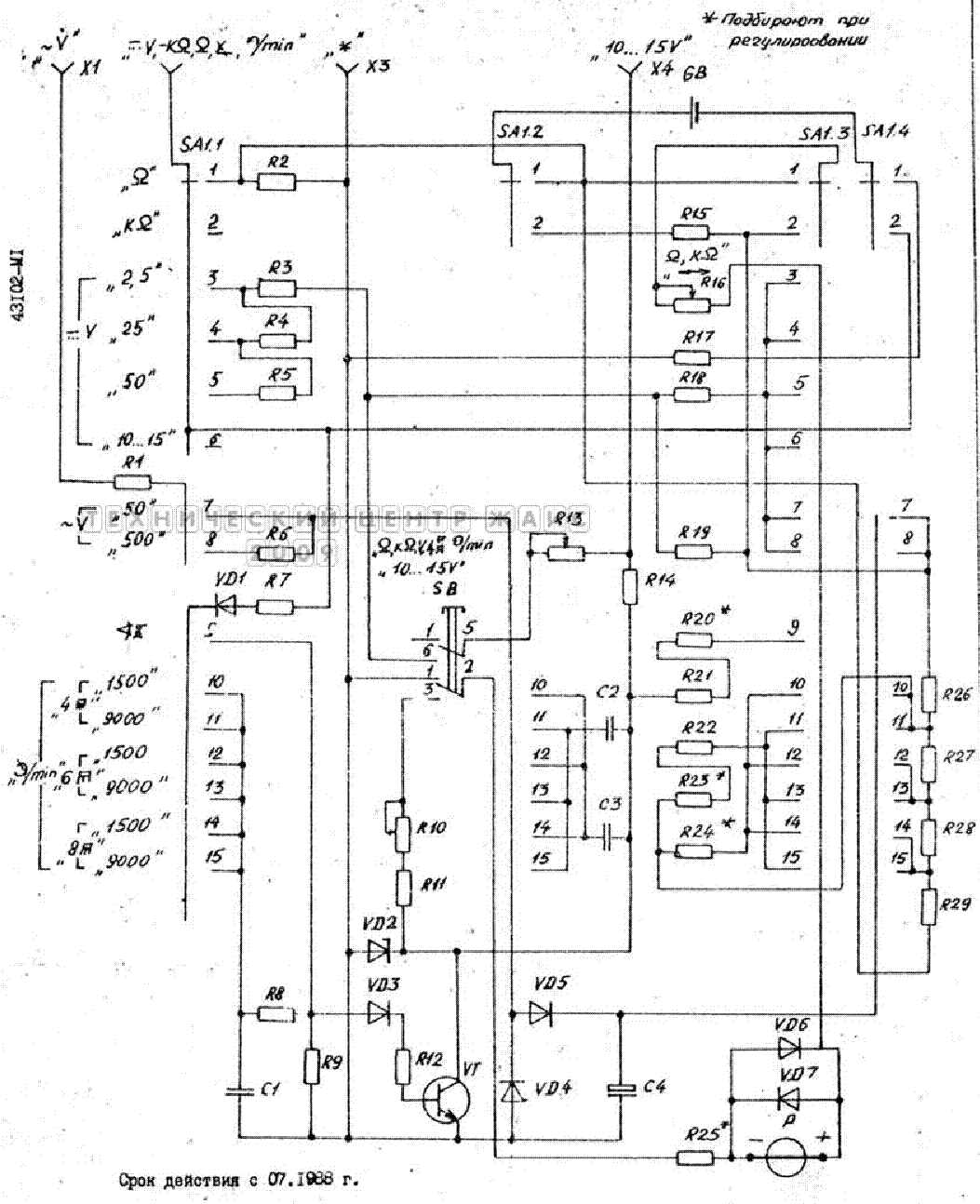
43102 M1 0788 Analog Multimeter Sch Service Manual Download Schematics Eeprom Repair Info For Electronics Experts
No comments for "Analog Multimeter Circuit Diagram Pdf"
Post a Comment